Bridge Instrumentation · High-Latitude Sensing
Navigation: Reading the Polar Picture
Navigating above the Arctic and Antarctic Circles tests every assumption built into standard merchant marine bridge electronics. Magnetic field lines dip nearly vertically into the Earth, conventional mechanical gyrocompasses lose their horizontal north-seeking directive force as the cosine of latitude approaches zero, and hydrographic charts in newly deglaciated fjords may rely on single-line lead soundings recorded a century ago.
To navigate safely, a polar bridge combines non-magnetic heading references, high-resolution surface radar processing, underwater acoustic scanning, and standardized satellite ice reconnaissance—while maintaining strict human oversight over sensor blind spots.
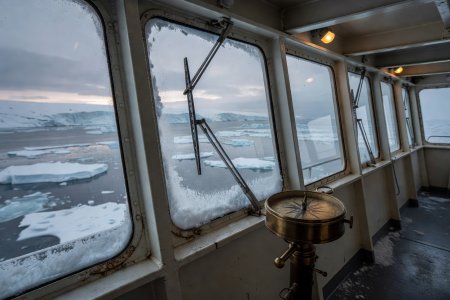
Fig 2.1 · Enclosed Heated Bridge Wing
Electrically heated laminated glass (150–300 W/m²) and heated pantograph wipers prevent rime frost from blinding visual ice conning.
Heading, Positioning & Charting Physics
Why Standard Compasses and Charts Fail Near the Poles
Fiber-Optic Gyros (FOG) & GNSS Compasses
The Problem: A traditional spinning-mass gyrocompass relies on Earth's rotation rate ($\Omega \cos \phi$). Above 70° latitude, horizontal earth rate becomes tiny and tangent-latitudinal speed errors climb rapidly, causing erratic heading drift above 80°.
The Solution: IMO Polar Code rules require two independent non-magnetic heading sources for ships operating above 80° latitude. Solid-state Fiber-Optic Gyrocompasses (using the Sagnac interferometric effect) paired with multi-constellation GNSS attitude receivers (GPS, GLONASS, Galileo) and grid navigation modes keep ECDIS stable without mechanical gimballing limits.
Forward-Looking Sonar (FLS)
The Problem: Many polar nautical charts carry Category of Zone of Confidence (CATZOC) D or U ratings, where glacial retreat has uncovered uncharted rock shoals and moraine sills.
The Solution: Retractable hull-mounted 3D Forward-Looking Sonar arrays project acoustic beams 300 to 800 meters ahead of the bow. However, bridge officers must recognize that sharp thermoclines and freshwater glacial meltwater layers refract sonar beams upward or downward, and heavy brash ice beneath the hull attenuates acoustic returns—requiring slow speeds (under 5–6 knots) or tender scouting in unsurveyed waters.
Radar & Electro-Optical Target Detection
Dedicated Ice Radar vs. Conventional Marine Radar
Standard IMO marine radars are engineered with clutter-suppression filters designed to erase small, stationary wave returns so that large steel ships and buoys stand out clearly. In polar waters, those very filters can accidentally erase the most dangerous target on the ocean: a low-freeboard glacial growler or bergy bit floating awash in sea clutter.
A dedicated Ice Navigation Radar processor taps into the raw video signal from the vessel's X-band (9.4 GHz, 3 cm wavelength) transceiver before standard sea-clutter suppression discards weak echoes. Using rapid scan-to-scan integration and sub-microsecond short pulses, the ice radar maps subtle differences in surface backscatter:
- Smooth First-Year Ice: Reflects radar energy specularly away from the antenna, appearing dark on the display except at its upturned fractured edges.
- Deformed Multi-Year Ice & Pressure Ridges: Contains weathered hummocks and air pockets that scatter X-band energy back toward the ship, appearing as bright, textured zones to be avoided.
- Open Water Leads & Polynyas: Identified as dark, uniform corridors threading between brighter deformed floes.
To prevent antenna gearboxes from stalling in freezing gale winds and rime accumulation, polar radar scanners require high-torque drive motors rated to −40 °C or radome enclosures heated internally.
Satellite Ice Charting & Communications
Decoding WMO Egg Codes and High-Latitude Comms
Strategic voyage planning relies on daily ice charts published by national ice services—including the Norwegian Meteorological Institute (MET Norway), the Canadian Ice Service (CIS), the Danish Meteorological Institute (DMI), and the U.S. National Ice Center (USNIC). These charts summarize ice conditions inside polygons using the standardized World Meteorological Organization (WMO) Egg Code.
| Egg Code Row | Symbol Variable | What It Measures | Example Interpretation |
|---|---|---|---|
| Top Row ($C_t$) | Total Concentration | Fraction of sea surface covered by ice, expressed in tenths (1/10 to 10/10) | 9+ indicates 9/10 to 10/10 consolidated pack; 4 indicates 4/10 open pack |
| Second Row ($C_a, C_b, C_c$) | Partial Concentrations | Tenths of thickest ($C_a$), second thickest ($C_b$), and third thickest ($C_c$) ice types present | 2 · 5 · 1 inside an 8/10 total means 2/10 thickest, 5/10 medium, 1/10 thinnest |
| Third Row ($S_a, S_b, S_c$) | Stage of Development | Thickness/age category corresponding directly to the partial concentrations above | 4. = Thick first-year ice (>120 cm); 7. = Old/multi-year ice; 1. = Medium first-year (70–120 cm) |
| Bottom Row ($F_a, F_b, F_c$) | Form of Ice (Floe Size) | Horizontal width of floes for each stage of development | 3 = Small floe (20–100 m); 5 = Big floe (500–2000 m); 8 = Fast ice |
High-Latitude Satellite Communications (Beyond GMDSS Area A3)
Geostationary satellites (such as traditional Inmarsat fleet services) orbit directly above the Equator. As a vessel sails poleward of 75°–78° N or S, the look-angle to the Equator drops below 5° above the horizon, causing masts, fjords, and atmospheric refraction to block the signal. Under GMDSS Sea Area A4 rules, polar ships carry HF radio installations paired with Low-Earth Orbit (LEO) constellations in polar orbits (such as Iridium Certus/GMDSS) to ensure uninterrupted distress alerting and SAR ice-chart telemetry all the way to 90° latitude.